


Mobile bridges

Nothing is certainly more suited to favouring social development both in terms of intelligence and civilization and in material economic interests, than the rapprochement and easy communication of the inhabitants of neighbouring territories. Every impediment to this intimate relationship and every difficulty opposed to social relations, produces an isolation that sadly affects the customs, alertness, morality and activity of a people so that in the Neapolitan and Sicilian Provinces vast territories are still maintained in a state almost wild from the lack of roads, bridges and other means facilitating communications and with these the association in the idea of spreading the works and the prosperous merit of the trade in arts and industry.
Part of the petition of 1867, signed by 98 inhabitants “of both banks of the Brenta”, sent to the mayor of the municipality of Oriago in order to obtain the construction of the pedestrian walkway in front of the church (ACM b.141, f. 67).
In 2000, a study on the movable bridges
along the Naviglio Brenta was published by the journal “Galileo” of
the Order of Engineers of Padua by Michele Questioni. This study identified the
state in which the structures were, briefly highlighting their main
construction features. It was decided to publish in this notebook the notes
published by “Galileo”, limited to the bridges present in the
municipal territory of Mira, trying as much as possible to update them and
enrich them in some points with the support of a documentary research in the
historical archive of the Municipality of Mira; the characteristics of the
cycle/pedestrian walkway built in 2006 in the Valmarana area have also been
published.
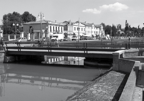
Pedestrian walkway in Mira (1863)


The work consists of a horizontal bearing structure formed by two iron columns, for balancing the bridge during the opening phase by means of tie rods. The project is by Ing. Carlo Bragato from Dolo, the construction of the structures by Fonderia Veneta Neville.
The elements of the main frame consist mainly of iron, steel and cast iron.
The bridge is 3.50 m wide, 16.76 m long, with swivelling spans of 5.36+11.44 m. The structure of the deck is made up of two triangular lattice beams that act as parapets.
It is stiffened by 19 iron crosspieces with a T section on which 7 secondary beams rest.
The 4 tie rods connecting the bridge heads and the pylons are integral with the rotation mechanism, to counteract the heeling effect when the bridge is in motion.
The static layout of the bridge, when closed, is a continuous beam on three supports, where the external supports are the shoulders; in the open position it is still a continuous beam on three supports, where the external supports are the tie rods.
The bridge was opened on 23 August 1863;
this date is revealed by an exchange of letters of 21 August 1863 between
Gambarare and Dolo municipal deputations: cf. A.C.M. b. 104, f. 641 (Editor’s
Note).
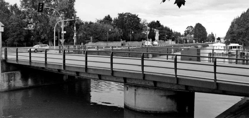
Mobile bridge in Mira (1965)


Located in front of the Mira municipality building, the bridge is used exclusively by vehicles, as pedestrians are prohibited from crossing and must use the nearby revolving pedestrian walkway.
In the closed position it is a structure with three supports, where the central one, the pier, is fixed, while those at the ends are sliding. When the bridge is open, the pivoting span behaves like a shelf subject to its own weight. The main supporting structure is made up of 16 IPE 330 UNI 5398-64 beams, placed at a distance of 0.50 m, which allow to contain the height of the deck. Furthermore, it can be thought that the set of 16 longitudinal beams, the crosspieces and the upper sheet form an orthotropic slab. The clear navigation aperture is 7.20 m. The length of the revolving span is 17.85 m (5.95+11.90), 7.50 m wide; the clear height with the bridge closed is about 1 m, the one required by the tender specifications was less than 16 cm.
To obtain the right balance of the structure, due to the different dimensions between the front and the rear, a counterweight was placed in the shorter part, made up of concrete blocks with incorporated turning shavings. The opening and closing manoeuvre is obtained in about 80 seconds, by means of an electric motor or in emergency cases, manually.
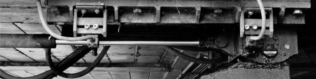
In the analysed project, the horizontal lock of the bridge in the closed position takes place with wedge devices controlled by a hydraulic jack. The vertical and longitudinal lock is formed by two wedge supports, at one end, controlled by hydraulic jacks; by a vertical pin at the pier, and by three rolls at the other end.
The designer was Ing. Oscar Kelemina
(Editor’s Note).
Mobile bridge over the Novissimo in Mira Taglio (1966)

The current bridge consists of a truss which in operation responds to the static layout of a continuous beam on four supports. The two farthest supports weigh on the shoulders, the two central ones on the pier. During opening, the weight is completely discharged on the pier, since two strong crossbars have been placed on the bridge that distribute the load on the wheel crown. Outside the pier, the two parts of the deck have very different spans, so it was necessary to place a counterweight at the end of the shorter side. The width that can be crossed by boats is 9.54 m when the bridge is closed, which becomes 8.50 m when the bridge is open. The useful width of the carriageway is 6 m, in addition to two sidewalks located at the ends, each one 1.25 m wide, raised above the road level. The revolving span is 24 m (8.50+15.50 m). The deck consists of 13 IPE 400 longitudinal beams connected by a series of crosspieces, two of which are located in correspondence with the pier and lean on the rolling rail; the space between them is octagonal to allow the distribution of the load on the rail. The deck sheet was laid over the longitudinal beams and crosspieces, forming the orthotropic slab.
Rotation takes place on 16 steel idlers
that run on two rails, kept at the exact distance from the centre of rotation
radially. In the longest part of the bridge, at the end, the supports are made
with two mobile wedges, whose height is adjustable. At the opposite end, the
supports consist of 3 wheels integral with the bridge. On the basis of the
documentation analysed, it appears that in 1988 the bridge underwent
extraordinary maintenance works as regards the opening system and the
restoration of degraded materials. It seems that there was a malfunction during
handling, caused by the imbalance of the permanent weights, which had the
resulting force outside the rotation circumference.
Mobile bridge in Mira Chiesa (1959)
The bridge is located in front of the Mira Lanza factory and was the main transit route for articulated vehicles. Originally the building consisted of: 2 main longitudinal beams at variable heights, from a minimum of 650 mm at the end, up to 1 m in correspondence of the rotation axis, placed at the edge of the carriageway; 7 INP 450 crossbeams that distribute the loads on the main beams; 4 INP 280 beams which unload on the crossbeams; the deck is completed by a stiffened metal sheet, covered with a bituminous wear layer.
In correspondence with the rotation axis, the crosspieces are arranged to form an octagon which guarantees greater stability to the structure during the opening phase. In order to improve the load-bearing capacity of the structure, interventions were necessary which mainly concerned: the reinforcement of the INP 450 crosspieces by adding a lower plate; the replacement of all secondary frame elements of the deck, with trapezoid-shaped box elements alongside the INP 280 beams; the replacement of the old sheet with a new Fe 430 sheet, 14 mm in thickness. The static layout of the bridge in the closed position is a continuous beam on three supports.
The bridge built in 1959 replaces the previous one erected by the municipality of Gambarare in 1833 under the patronage of the Archduke of Austria Giuseppe Ranieri of Habsburg. “At Mira there are two rotating iron and wooden bridges, which connect it one with the Brentella, the other with Gambarare; and after crossing the second one, we will enter the ancient Podestà office of Gambarare or Fossa Gambaria.”
(C. Cantù, History of Venice and its
Province, 1859) (Editor’s Note).
Continuing along the Naviglio Brenta towards Venice, near the Villa of the same name, we find the revolving bridge of Valmarana. This construction dates back to the late nineteenth century but was dismantled only in 1966 (from Piazza Mercato, see below) and reassembled in its current position.
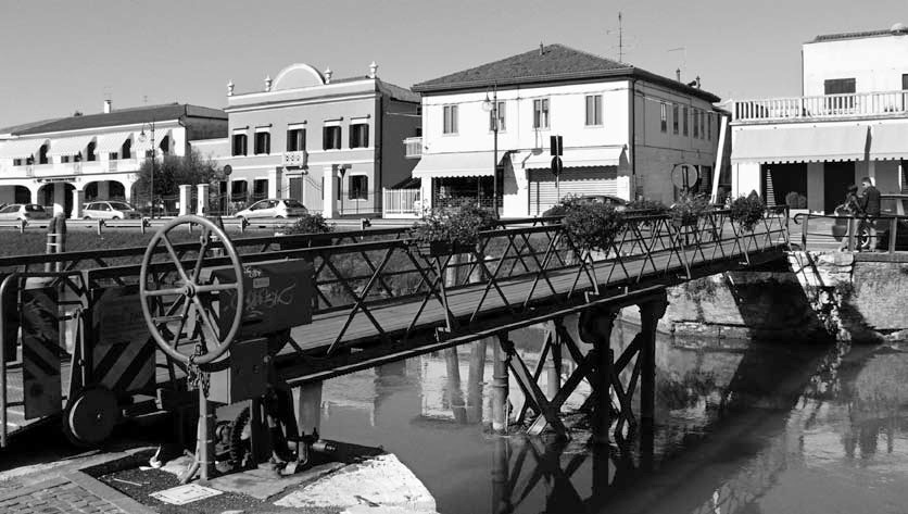
Mobile bridge in Mira Valmarana (1880)


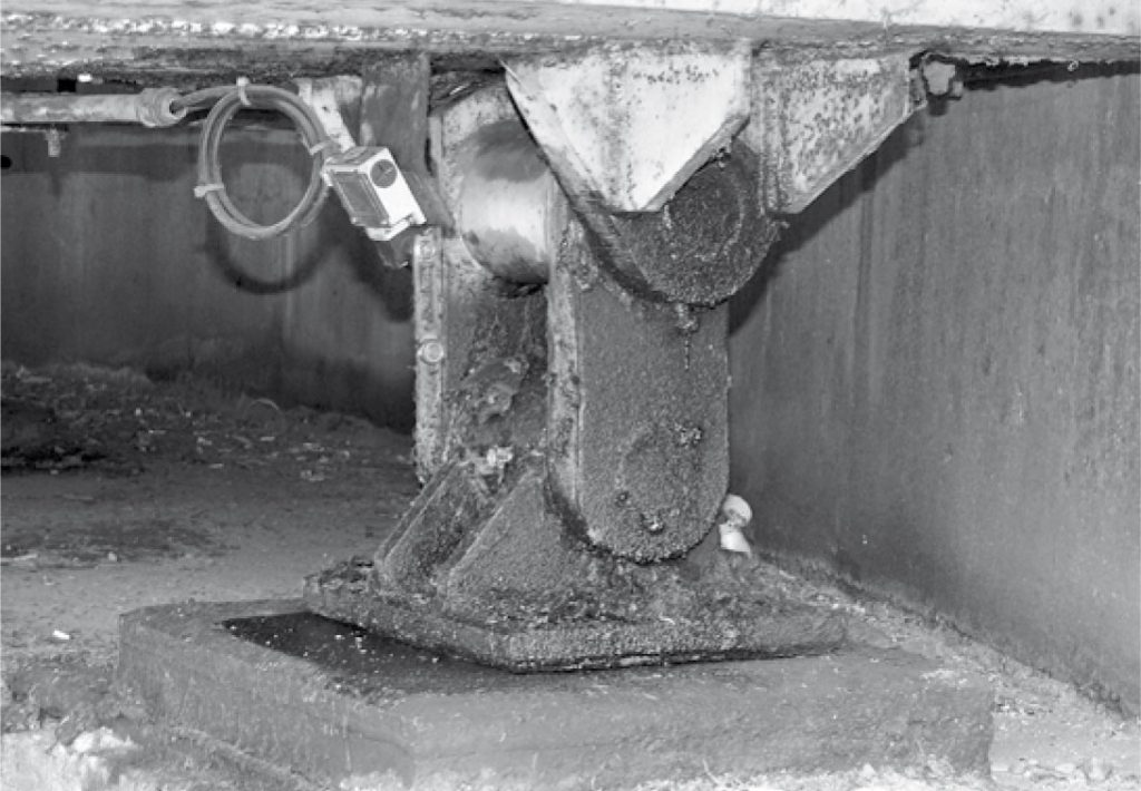
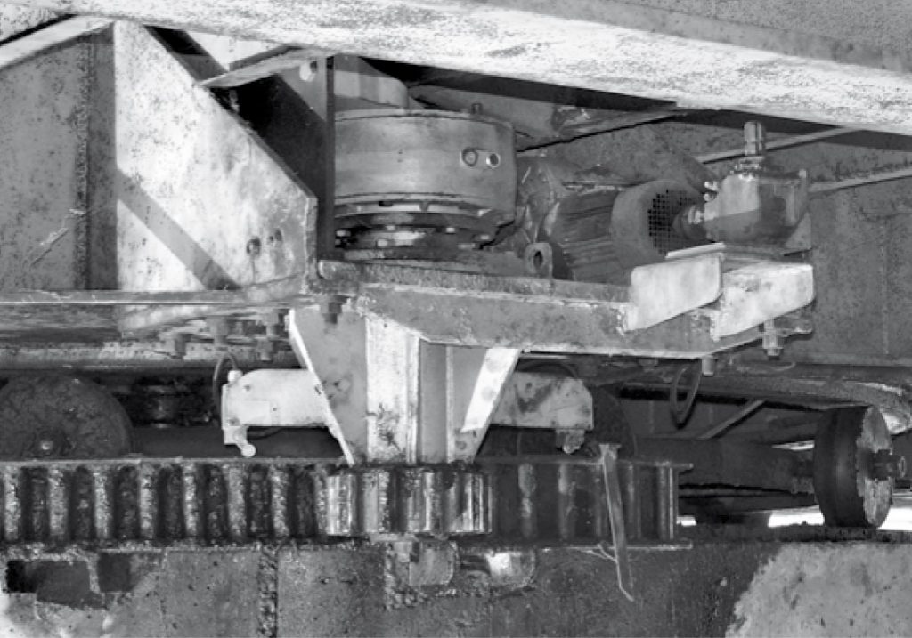
It is 21.97 m long, 3.60 m wide, has a narrowing to limit the maximum width of vehicles in transit, which occurs in alternating directions. The revolving deck is made up of two longitudinal lattice beams on which 25 iron crossbars rest that support the wooden beams, on which the upper planking rests. The span is divided into two equal parts by the central pier; its position is such that although it is a bridge with two equal spans, therefore perfectly balanced, it leaves, in the open position, two navigation gaps of different sizes. The central pier is circular in reinforced concrete. The rotation takes place on eight wheels that run on a rail with a diameter of 3.30 m, integral with the pier.
The bridge was designed by Dr. Pietro Gilli and built by the Paolo Rocchetti company from Padua.
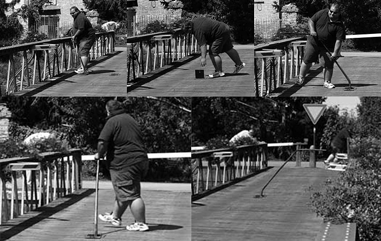
Handling is manual; the operator unlocks
the vertical locking wedges by operating a lever on the parapet, then inserts a
crank in the pinion axis which is located within a small trap door in the
centre of the bridge and pushing it while walking round, sets in motion the
gears that transmit the rotation to the structure until it is parallel to the
watercourse thus freeing the two spans for the passage of boats. (Editor’s
Note)
Mobile bridge of Piazza Mercato in Oriago (1977)
The swing bridge, designed by Ing. Guido Ravenna, consists of two steel structures, one of which is revolving, with a centre of rotation on a circular pier in reinforced concrete, and one is fixed.
These structures rest on shoulders supported by poles planted in reinforced concrete. It has a total length of 29.42 m, a width of 9.30 m, and a navigation gap of 7.50 m.
The framework of the bridge consists of two longitudinal beams with a distance of 6 m, made of a welded structure, with a constant omega section in the section near the pier that tapers towards the ends.
The tapered section has been designed to
withstand the greatest stresses when the bridge is open, when the static layout
is a double bracket. The beams were made with two vertical cores, an upper jack
arch and two lower plates, in order to create an easily accessible open section
for welding.
Pedestrian walkway in Oriago (1872)
Located in the town of Oriago, in front of the church, it serves as a pedestrian crossing of the Naviglio Brenta.
In past centuries, before this work was built, there was a “passing station” at the same point, operated with a ferry service, to connect the opposite banks of the river. It is a sliding structure on rails that partially fit into the side street.
It is built in iron, consisting of two lattice beams, on which the pedestrian level formed by wooden crossbeams, and the upper planking rest. It is 17.50 m long and 1.50 m wide, is supported by a pylon in the centre, formed by four columns with a tubular section, in cast iron, fitted at the foot with screws for sinking. The columns are connected to each other with St. Andrew’s crosses that stiffen and distribute any shocks during manoeuvres.
For sliding, four cast iron wheels are connected, with cast elements, to the capitals of the columns and have a hollow in the extreme part that prevents any disruptions. In addition to the four wheels of the pier, two others, connected at the end of the deck beams, run along the side street.
The opening takes place by activating the mechanism located on the right bank of the Naviglio, obtaining the sliding of the structure on special rails.
The walkway was designed by Ing. Carlo Bragato and built with the authorization of the Minister Secretary of State granted on 13 October 1870 (A.C.M. b. 141, f. 67).
From a shipping note from the Neville foundry, dated June 13, 1872, for the supply of “No. 2 cast iron wheels turned to his sample, with a turned iron pin, one of which belongs to him “(A.C.M. b.137, f. 43), it can be deduced that the inauguration of the bridge did not take place before that date. From the Bragato drawings, it can be seen that the actuation for the manual opening of the bridge was not provided with a wheel, but with a double crank.
In 2006, a modification was made to the
opening mechanism, equipping it with electric action, the rails in the road
were removed and the two relative wheels were raised, a roll was inserted at
the end of the deck beams, in the centre of the pedestrian floor under the
walkway slide, obtaining the sliding of the structure directly on the road
asphalt without however providing a special level beam designed to stiffen the
sliding surface during the opening and closing phases (Editor’s Note).


Mobile bridge in Oriago (1990)
Built along the Naviglio Brenta, on a project by Ing. Gianni Munari, it replaces a previous one (Editor’s Note: built between 1961 and 1962) no longer sufficient to meet the needs of traffic. It has a length of 23.00 m and a width of 11.00 m, with two carriageways of 4.5 m each and two sidewalks of 1.50 m each. The pier is located on the right side of the Brenta, so as to obtain a navigation passage of 7.50 m.
The main structure is in steel, consisting of: two main longitudinal beams in welded plates, which support the sidewalks; eight crosspieces, two placed in correspondence with the rotation pier, with a greater height, to make the structure more stable during the opening phase; two longitudinal crosspieces. The upper sheet is stiffened by tiles. A waterproof covering and the wear surface are laid over the deck sheet.
At the rear of the revolving deck there is a counterweight for balance, due to the different dimensions between the cut and the breech.
Movement takes place by activating the controls placed on a special panel in the parapet, above the pier. It is possible to move the bridge both automatically and manually, on the basis of a safety device with a programmed path that allows the execution of the next operation only if the previous one has been completed.
The bridge was inaugurated on August 18,
1990 (Editor’s Note).
Mobile bridge in Malcontenta (1967)
It consists of a metal structure, with a reinforced concrete pier positioned near the right bank of the Naviglio, and shoulders. The carriageway is 22.00 m long and 6.00 m wide and the sidewalks 1.25 m.
It is one of the swing bridges in which the free height, in the closed position, is very limited, however reflecting the conditions foreseen by the tender specifications that imposed, between the upper water level of the Naviglio and the intrados of the bridge, in correspondence of the entire navigable area, 0.90 m of space.

The main structure, according to the original project, is made up of thirteen IPE 400 beams placed at a distance of 0.50 m, and eight crosspieces. In correspondence with the pier, where the rotation takes place, 5 IPE 400 beams are arranged to stiffen the structure. This arrangement allows to reduce the height of the deck, forming, together with the upper sheet, an orthotropic slab. In the closed position, the static layout is a structure with three supports, the central one of which, the pier, is fixed and those at the ends are sliding. In the open position it behaves like a shelf subject to its own weight. Due to the different dimensions between the front and the rear, a counterweight was placed in the shorter part, consisting of concrete blocks with turning chips.
Built to replace the one designed around 1865 by Ing. Carlo Bragato.
It underwent changes around 1990. (Editor’s
Note).
Cycle and pedestrian drawbridge in Mira Valmarana (2006)

The bridge, inaugurated in December 2006, is the latest building in terms of time; it is 23 m long, 2.5 m wide, weighs 180 q and the maximum lifting angle is 30 degrees.
Designer: Eng. Flavio Zanchettin. Builder: Costruzioni Metalmeccaniche Zara in Dolo.
For this work, not registered by the magazine “Galileo”, we copy part of the structural report extrapolated from the specifications.
“The structure in question consists of two double-T welded beams with variable height.
The lower and upper flanges of each beam, made up of specially calendered plates, have a thickness of 30 mm while the core has a thickness of 15 mm. These beams are connected at the top to each other at a constant pitch of 1.5 m by 2 UNP 100 coupled profiles; at the same time, the cores are stiffened both externally and internally by 10 mm thick plates. Every 3 m there is also a lower connection made with a double pair of profiles L 80x80x8; a K-type bracing is also created, by means of 2 coupled profiles 75x50x6 which converge in the middle of the lower rod.
Parallel to the walking surface there is a system of zig-zag bracings made with single profiles
L 110x110x10 that block any lateral sliding.
The deck is bound at one end by a pair of spindles on bushings that block the movements along each direction and only allow the rotation that enables the opening and closing of the bridge. This latter task is carried out by a hydraulic mechanism consisting of a pair of pistons whose liners, hinged on the right side shoulder, have an external diameter of 245 mm and a bore of 200 mm; the rod has a diameter of 140 mm and a stroke of 1440 mm”.


